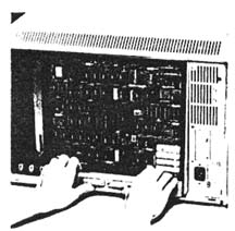
Figure 8 To remove the card cage,
brace your thumbs and pull straight back.
computer, brace your thumbs underneath and pull straight back as shown in
Figure 8.
The mother board is fixed to the bottom of the cage and there may be three
or four removable cards (depending on how much memory you have) arranged
vertically, from back to front, as shown in Table 2.
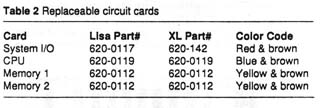
Note that part numbers beginning with 620 refer to a complete circuit card
(defined as a plug-in circuit board with all the parts on it), not an empty
board, which is always referred to by another number beginning with 820.
All four cards fit into tongue and socket connectors on the mother board.
To remove a card, loosen the color coded bails and pull straight up. The
four cards slip in and out easily, and the design makes it impossible to
reinstall them backwards; although, it's very easy to get confused. Note
that the CPU card faces backward, while the System I/0 card faces forward.
If the CPU card offers the least bit of resistance when you try to put it
in, it means you're holding it wrong. Don't force anything! Check the color
codes as illustrated in Figure 9. The Memory cards and the CPU card on Lisas
and Mac XL's are interchangeable. The System I/0 cards are not (The XL I/0
card will work in a Lisa but a Lisa I/0 card will not work in an XL) Physically,
they fit, but electrically there are problems with disk-drive control. If
you just bought a used Lisa, or if you're
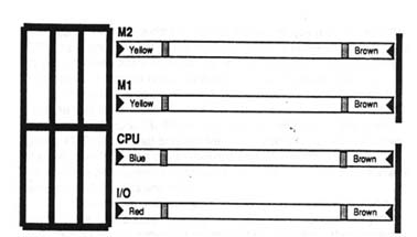
Figure 9 Top view of the Usa/XL
card cage. Bail colors indicate proper orientation.
restoring a Lisa and can't seem to get it going, it's important to check
for the correct System I/0 card. The differences are shown in Figures 10
and 11. ROM cliff erences on the I/0 may also be present if you have upgraded
you computer with a 800K floppy drive. If a screen modification kit is present
in your computer the
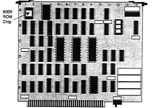
Figure 10 The Lisa I/0 card. Note
the battery pack (lower right) and the AMD 9512 coprocessor socket (upper
right).
Next
Back
Contents