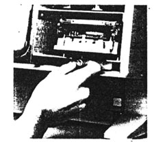
Figure 2 To remove the entire disk drive cage, loosen this retaining nut until it springs free and then pull straight back.
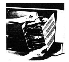
Figure 3 When removing the disk drive assembly take care not to snag or overextend the drive cables. There's not much slack!
and loosening four screws at the bottom. Hard drives, when present, are held by five or six screws along the side.
400K Sony drives are identified by part numbers beginning with OAD34V. 800K Sony drives are identified by part numbers beginning with MPF51 W. You might also find an 800K Chinnon or Fujitsu drive in a Lisa. Original 10MB Widget drives are marked "Apple computer." Other internal hard drives might be marked "Fujitsu," "Kalok," "Miniscribe," or "Seagate", etc. For reference, write down the make and model numbers of whatever drives you find.
The rear panel is held on by two thumbscrews. Turning the thumbscrew counterclockwise disengages a metal retaining tab. Note that it's not necessary to remove the thumbscrews. With a little loosening, you can pull the rear panel back and lift it away. This procedure is shown in Fig. 4.
Removing the rear panel opens a second safety switch 'in the upper right-hand corner of the computer located on the powersupply. If the computer is on, removing the rear panel also turns
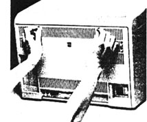
Figure 4 To remove the rear panel, first disconnect the power cord and all peripheral cables, then turn the thumbscrews counterclockwise, pull slightly, and lift at an angle.
it off. Safety switches protect the computer as well as the operator. It's possible to defeat safety switches (the cap of a ball point pen works well) but be careful. Removing cards without turning the power off first is a surefire way to destroy them.
Note that pressing the on/off switch or removing the covers (engaging the safety switches) does not remove all power to the computer. The only way power can be completely removed is by unplugging the line cord.
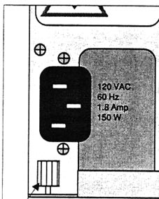
Figure 5 To remove the power supply, loosen the finger nut and pull straight back. Note that the nut is located approximately 1/2 inch from the edge of the chassis.