1 . If the set is on, power down normally and switch off the power.
2. Physically disconnect the power cord from the wall outlet. If you're the least bit hesitant about discharging the CRT, leave the set disconnected overnight. By the next morning, most, if not all, of the high-voltage charge will have dissipated.
3. Disconnect all peripheral cables, and remove the rear cover from the back of the computer. Refer to Figure 4.
4. Remove the card cage and the CPU board. Refer to Figures 9 to 10.
5. Remove the existing 20-pin video ROM from location C6 on the CPU board. Replace it with part number 341-0348.
6. Remove the 28-pin boot ROM from location D12 on the CPU board. Replace it with part number 341-0347.
7. Remove the boot ROM from location D 14. Replace it with part number 342-0346.
8. Replace the CPU board and put the card cage aside. Don't reinstall it just yet.
9. Remove the top cover. Refer to Figure 13.
10. Remove all rings, watches, and jewelry. Put on safety goggles.
11 . With one hand behind your back, discharge the CRT through a 10-meg resistor.
12. Unplug the green and yellow CRT (yoke) to P2 cable from the video board. As illustrated in Figure 29, P2 is located
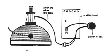
Figure 29 XL screen kit wiring details.
approximately halfway down the left side of the board.
13. Plug the yoke cable into the new screen kit transformer. Plug the new transformer into P2.
14. The new transformer attaches to the outer wall of the diskdrive chamber with double-sided tape. Clean the area, and attach the transformer as shown in Figure 30.
15. Locate the six adjustment potentiometers labeled "CONT.," "HOR. PHASE," "HEIGHT,' W. HOLD," "WIDTH," and "V. LIN" which are at the top of the video board. As shown in Figure 31, these adjustments have been sealed at the factory and will have to be unsealed and readjusted for use with the screen kit.
16. With a sharp razor knife, carefully remove all of the sealant *
The key word here is all. It's not enough just to break the
sealant. Any glob that remains may artificially limit the
adjustment, making it impossible to properly realign the
screen. For best results, every glob of sealant must be
removed!
17. Refer to Figure 9. Slide the card cage back into the Lisa, and reconnect the power cord. Turn on the Lisa/XL.
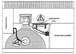
Figure 30 The new coil attaches to the outer wall of the disk-drive chamber with double-sided tape.